
Note: This article is not complete yet. I am intending to add a wiring diagram (whenever I get around to re-installing Visio on my computer) and a build video (whenever I get around to making it).
List of parts:
- GPS module
- Data logger (https://thepihut.com/products/fermion-serial-data-logger?variant=41607027949763)
- Voltage buck (optional) (https://www.amazon.co.uk/dp/B08HQQ32M2?psc=1&ref=ppx_yo2ov_dt_b_product_details) (10 pack but only 1 is required)
- 1s LiPo (optional)
- SD card
The links above are to the components I used but any suitable alternatives could be used.
If you are going to use a dedicated 1s lipo then the voltage buck is required to convert the LiPo voltage to a stable 5v output. Alternatively the unit can be powered from any 5v supply (e.g. flight controller 5v pin).
Build instructions:
- Configure your data logger (the description below is for the fermion data logger linked to above).
- Format your SD card to FAT 32 and insert it in the data logger
- Insert the SD card into the data logger and connect a 5v power supply for a minute or two (this is to allow the data logger to write a default configuration file to the card)
- Remove the card and insert it into your computer.
- Edit the config.txt file to set the data rate and output filetype (CSV is preferred).
- Baud=02,FileNum=00001,FileFormat=1,Time=0
- The important settings is Baud=02 (or whatever baud rate your GPS module defaults to):
- 00: 2400
- 01: 4800
- 02: 9600
- 03: 14400
- 04: 19200
- 05: 38400
- 06: 56000
- 07: 57600
- 08: 115200
- 09: 128000
- 10: 230400
- 11: 512000
- 12: 1000000
- FileFormat=1 is for CSV output files.
- Save the configuration file, eject the SD card form your computer and put it back in the datalogger.
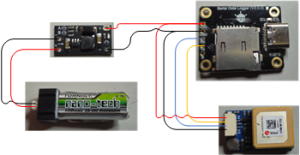
- Make the connections
- Data logger
- +5v to Voltage buck +5v output (or Flight Controller 5v output.
- Gnd to Voltage buck Gnd output (or Flight Controller Gnd)
- TX to GPS module RX (not really required)
- RX to GPS module TX
- GPS module
- +5v to Voltage buck +5v output (or Flight Controller 5v output.
- Gnd to Voltage buck Gnd output (or Flight Controller Gnd)
- RX to Data logger TX (not really required)
- TX to Data logger RX
- Voltage buck (if used)
- Make sure you configure the output for 5v. The item linked to above has a default output of 12v!
- +5v out to +5v on Data logger & GPS module
- Gnd out to Gnd on Data logger and GPS module
- Vin to Battery +
- Gnd in to Battery -
- Data logger
- Check the connections! (I did fry one GPS module by accidentally reversing the + & - power wires!)
- Test
- Power on the unit and wait for the GPS module to log onto some satellites (the GPS LED on the GPS module will illuminate or flash).
- Walk around a bit to get some data.
- Power off the unit
- Remove the SD card and put it in your computer.
- Find the data file (in my case File00001.csv).
- Upload it to the converter program.
- Download the converted file.
- Open the converted file in Google Earth
- If all is well you should see the path you took when walking around.